You plug the OBD2 scanner into the car’s port, and it talks to the vehicle’s computer to find faults and live data. It reads standardized error codes and live sensor data so you can see what’s wrong and where to start fixing it.
This tool lets you check engine status, capture fault codes, and watch sensors in real time without guessing. It works on most cars by following a common protocol, and some scanners can access deeper, maker-specific info for tougher problems.
A good scanner saves time and money by pointing to likely causes before you open the hood or call a shop. They range from simple code readers to advanced tools that run tests, clear codes, and help diagnose tricky faults.
Key Takeaways
- Connects to the car’s computer to read fault codes and live data.
- Shows sensor readings and standardized codes to narrow down issues.
- Ranges from basic code readers to advanced diagnostic tools.
Fundamental Concepts of OBD2
This section explains how the car’s diagnostics system monitors sensors, stores trouble codes, and lets a scanner read live data and perform tests. It covers the system’s purpose, how OBD2 improved on OBD1, and the main communication protocols used today.
On-Board Diagnostics Overview
OBD2 is the vehicle’s electronic health monitor. It watches engine, transmission, and emissions systems through sensors like oxygen, MAP, MAF, crankshaft position, and coolant temperature. When a sensor value falls outside expected range, the system logs a Diagnostic Trouble Code (DTC) and often turns on the malfunction indicator lamp (MIL).
A scanner connects to the standardized 16-pin port to read DTCs, view live sensor data, and reset the MIL. Scanners can also show freeze-frame data — a snapshot of conditions when a fault occurred — which helps pinpoint when and why the fault happened. Many modern scanners run active tests to command components on or off for diagnosis.
Evolution from OBD1 to OBD2
OBD1 systems were early, manufacturer-specific systems with limited standardization. They often required special tools and knowledge for each brand. OBD2, mandated in the mid-1990s, created a common connector, standard codes, and a framework for emissions monitoring.
OBD2 added rules for continuous and non-continuous monitoring, standard DTC formats (like P0123), and stricter emissions-related tests. This change made it easier for independent shops and DIYers to diagnose cars across many makes. OBD2 also expanded access to live data streams and enhanced readiness monitors used for emissions testing.
Key OBD2 Protocols
OBD2 supports several communication protocols that determine how the scanner and car talk. Common protocols include:
- ISO 9141-2: Used on older European and Asian cars; slower, simple signaling.
- SAE J1850 PWM/VPW: Found on older Ford (PWM) and GM (VPW) models.
- ISO 15765/ISO 14229 (CAN/UDS): Modern vehicles use CAN bus (ISO 15765) and higher-level UDS commands for fast, robust diagnostics.
A scanner must support the vehicle’s protocol to read data. Many modern scanners auto-detect the protocol. Knowing the protocol helps choose the right tool for advanced tasks like module programming or manufacturer-specific tests.
Core Components in OBD2 Systems
This section explains the main parts that let a scanner read and act on vehicle data. It covers the vehicle computer, the codes the system stores, and the physical connector used to access that data.
ECU Integration
The Engine Control Unit (ECU) is the central computer that monitors and controls engine functions like fuel injection, ignition timing, and emissions systems. It reads inputs from sensors — such as mass airflow, oxygen, coolant temperature, and crankshaft position — and uses that data to adjust actuators. The ECU also stores fault conditions and status information when it detects values outside expected ranges.
OBD2 scanners communicate with the ECU over vehicle networks (CAN, ISO, or manufacturer protocols). The ECU responds to standard requests for live sensor data, freeze-frame records, and control commands if the scanner supports active tests. Access level varies by vehicle; some ECUs restrict certain commands for safety and security.
Diagnostic Trouble Codes
Diagnostic Trouble Codes (DTCs) are standardized codes the ECU stores when it detects a fault. Each DTC is alphanumeric and follows the format P0xxx, P1xxx, etc., where the first character indicates the system (P=powertrain). A code identifies the general area of the fault, but technicians must use live data and context to pinpoint the exact cause.
DTCs come in two main types: current (active faults that trigger a warning light) and pending/historic (intermittent or previously cleared faults). Scanners can read, clear, and sometimes translate DTCs into plain-language descriptions. Proper diagnosis uses DTCs plus freeze-frame data and live sensor values to avoid replacing parts unnecessarily.
Data Link Connector
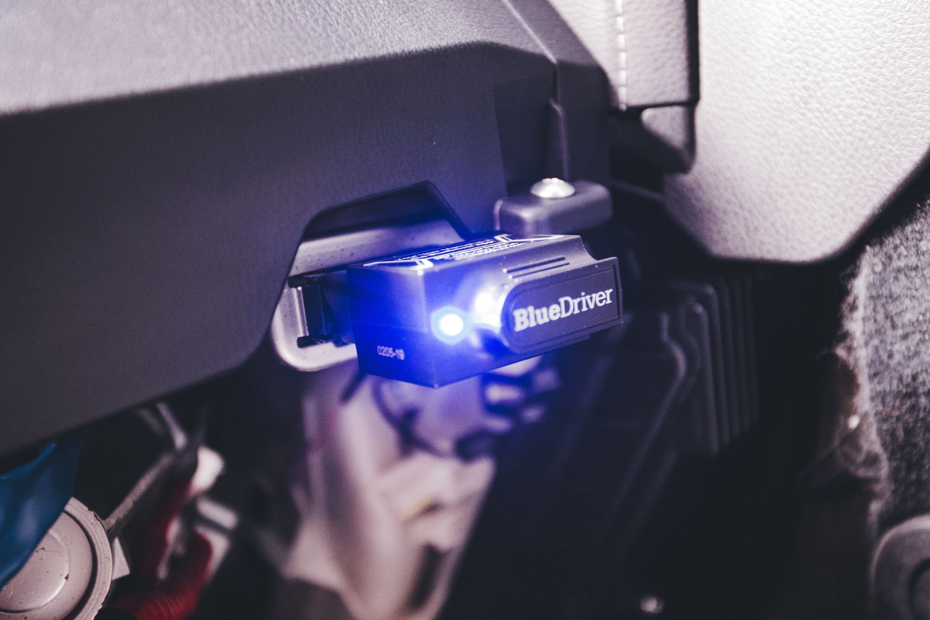
The Data Link Connector (DLC), commonly the 16-pin OBD2 port, provides the physical connection between the vehicle and the scanner. It usually sits under the dashboard on the driver’s side and follows a standard pin layout for power, ground, and communication lines. Knowing pin assignments helps when testing wiring or using bench tools.
The DLC supports multiple protocols, so a compatible scanner must detect or be set to the vehicle’s protocol. Some pins carry CAN high/low for modern vehicles, while others map to older ISO or manufacturer-specific lines. The connector also supplies 12-volt power and ground to the scanner, enabling handheld tools to operate without an external power source.
Scanner Device Architecture
The scanner ties together physical connectors, processors, and user interfaces to read car systems and run tests. It must translate vehicle network signals, run diagnostic software, and show results to the user quickly and reliably.
Hardware Elements
The hardware centers on the OBD-II connector (usually a 16-pin DLC) that supplies vehicle power, ground, and data lines like CAN high/low, K-line, or ISO pins. A transceiver chip converts these bus voltages to logic-level signals the device can process.
A microcontroller or SoC runs the device, handling protocol timing, message framing, and data buffering. Many units add an EEPROM or flash to store firmware and vehicle-specific maps.
Power regulation circuits protect against voltage spikes and provide stable 5V or 3.3V rails. Optional components include an OLED/LCD display, buttons, LEDs, Bluetooth/Wi‑Fi radios, and an SD card slot. High-end scanners also include relays or MOSFETs for active test outputs.
Firmware and Software Features
Firmware implements protocol stacks (CAN, ISO-TP, KWP2000, etc.), error handling, and the command set that forms the scanner’s API. It handles PID requests, DTC reads, clears, freeze-frame capture, and real-time sensor streams. Timing and retry logic matter because vehicle networks have strict timing windows.
The user-facing software parses raw frames into human-readable codes and live graphs. It maps universal and manufacturer-specific DTCs to descriptions, provides freeze-frame data, and logs sessions. Bluetooth/Wi‑Fi dongles often present an AT-like command layer; mobile apps then decode and display data. Updatable firmware and code databases let the scanner add new vehicles and fix protocol bugs.
Communication and Data Retrieval
The scanner connects to the vehicle’s OBD2 port and asks specific modules for information. It reads stored fault codes, requests real-time sensor values, and can capture a snapshot of conditions when a fault occurred.
Reading Vehicle Data
The scanner sends standardized request messages over the vehicle network and waits for module responses. Each response includes a Parameter ID (PID) or a Diagnostic Trouble Code (DTC). The scanner decodes hexadecimal messages into readable items like engine RPM, coolant temp, or stored trouble codes.
Communication uses protocols such as CAN, ISO, or SAE. The scanner selects the correct protocol or auto-detects it, then polls the powertrain control module (and other modules) for supported PIDs. Results often show code numbers plus brief text like “P0301 — Cylinder 1 Misfire.”
Live Data Streaming
Live data streaming shows changing sensor values continuously. The scanner requests PIDs repeatedly—typically several times per second—and displays values like vehicle speed, oxygen sensor voltage, and fuel trim. This helps diagnose intermittent issues or confirm repairs.
Some scanners log this stream to a file or graph it in real time. Higher-end tools let the user set sample rates, record sessions, or run multiple PID requests in parallel. The limiting factors are bus bandwidth and the vehicle module’s response speed.
Freeze Frame Functionality
Freeze frame captures a snapshot of selected sensor values when a DTC sets. It records conditions such as engine load, throttle position, and engine temperature at the moment the fault occurred. This snapshot helps link a code to actual operating conditions.
The scanner reads the freeze frame from the module’s memory and displays timestamps and values. Technicians use this to determine whether a fault happened under idle, cruise, or heavy load, which narrows down likely causes.
Interpreting Diagnostic Information
This section explains how to read fault codes, reset them, and check live sensor data. It focuses on what each piece of information means and how a user can act on it.
Decoding Trouble Codes
A trouble code (DTC) looks like P0301 or C1234. The first letter shows system: P = powertrain, B = body, C = chassis, U = network. The first digit shows if it is generic (0) or manufacturer-specific (1). The next digits identify the subsystem and specific fault.
Code readers will also provide a short description like “P0171 System Too Lean Bank 1.” The description narrows the fault, but it does not give the root cause. Technicians use the code as a starting point: check freeze-frame data, read live sensors, and follow manufacturer test steps. Always verify with measurements before replacing parts.
Clearing Fault Codes
Clearing codes removes stored DTCs and turns off warning lights. Most scanners offer a “Clear/Erase” command that also deletes freeze-frame data and readiness monitors. After clearing, the vehicle must be driven through a drive cycle so the ECU can re-run its self-tests.
Do not clear codes before diagnosing. Clearing hides data that helps find intermittent faults. If a code returns immediately after clearing, the problem is active. If it returns only after specific conditions, note those conditions for targeted testing.
Analyzing Sensor Readings
Live data shows values like engine RPM, coolant temp, O2 sensor voltage, and short/long trim. A scan tool can display these values in real time, as numbers or graphs. Compare readings to expected ranges in the service manual.
Look for trends and relationships: a high short fuel trim with low fuel pressure points to fuel delivery; a low O2 voltage with high trim suggests a lean condition. Pay attention to units and update rate. Record data during the fault reproduction to capture transient issues and support accurate repair decisions.
Common Applications and Use Cases
An OBD2 scanner helps check vehicle health, confirm emission readiness, and diagnose drivability problems. It reads fault codes, shows live sensor data, and can clear codes after fixes.
Routine Maintenance Checks
Technicians and DIYers use scanners to monitor basic systems before they fail. They read Diagnostic Trouble Codes (DTCs) and live data like coolant temp, fuel trim, and RPM to spot early signs of wear. For example, high long-term fuel trim numbers can point to a vacuum leak or a weak fuel pump.
Scanners also track service reminders and reset maintenance lights after oil changes or brake service. Simple active tests let a user run a component — like a fuel pump or EGR valve — to confirm operation without removing parts. This saves time by narrowing down what actually needs replacement.
Emissions Readiness Testing
An OBD2 scanner checks whether a vehicle’s emission systems are ready for inspection. It reads readiness monitors (catalyst, O2 sensor, EVAP, etc.) and shows which tests passed or failed. If monitors show “not ready,” the car may not pass a smog check even if no DTCs are present.
The scanner also retrieves emission-related codes such as misfire, rich/lean conditions, or EVAP leaks. Technicians use freeze-frame data and live O2 or lambda readings to find the root cause. Clearing codes without fixing the issue will reset monitors, which often delays passing an emissions test until driving cycles complete.
Troubleshooting Performance Issues
When a car runs rough, lacks power, or stalls, a scanner gives targeted clues. It captures stored DTCs and freeze-frame snapshots that record engine conditions at the moment a fault happened. This helps identify whether a problem is fuel delivery, ignition, or sensor-related.
Live data lets a mechanic watch readings while driving or during a road test: fuel trim trends, misfire counts per cylinder, intake air temp, and boost pressure, for example. Advanced scanners also run active tests or bi-directional controls to exercise parts like throttle bodies or solenoids, proving whether a component responds correctly before replacement.
Limitations and Considerations
Users should check vehicle compatibility, know that code reading may not pinpoint exact fixes, and avoid common setup mistakes. The scanner’s capabilities depend on its model and the car’s electronics.
Compatibility Factors
Different vehicles use different protocols and manufacturer-specific codes. A basic OBD2 scanner reads standard SAE codes, but many late-model cars require enhanced or dealer-level scanners to access ABS, airbag, transmission, or body-control modules.
Physical fit matters. Most cars use the same 16-pin OBD2 port, but older or imported vehicles sometimes need adapters. Software updates on the scanner can add support for newer models, so users should update the device before diagnosing a newer car.
Power and communication standards vary by region and year. Confirm that the scanner lists the car’s make, model year, and supported protocols (e.g., CAN, ISO9141, KWP2000) to avoid wasted time.
Scanner Accuracy
An OBD2 scanner reads stored trouble codes and live sensor data, but codes only point to faults, not always causes. Misleading codes can result from secondary failures, damaged wiring, or intermittent faults that don’t log consistently.
Higher-end scanners provide freeze-frame data, live graphs, and bi-directional tests that improve diagnostic accuracy. Inexpensive or generic tools might show the correct code but lack enough data to diagnose timing, wiring, or component-level issues.
Accuracy also depends on proper sensor readings. Faulty sensors give false symptoms, so technicians should verify sensor data with multimeters or oscilloscope tests when needed. Regular scanner firmware updates help maintain accurate interpretations.
Potential User Errors
Users often misinterpret codes as final diagnoses. Reading a P0301 code (cylinder 1 misfire) doesn’t tell whether the problem is a spark plug, injector, compression, or wiring issue. Users should follow step-by-step tests rather than assuming a single component failed.
Connection mistakes are common. Loose OBD2 plugs, low vehicle battery, or using the wrong app with Bluetooth adapters can block communication. Users should ensure firm connection, sufficient battery voltage, and correct app-device pairing.
Improper use of live data and tests can cause harm. Running active tests or resetting systems without knowing consequences may disable safety features or erase useful diagnostic history. Users should consult service manuals before performing advanced procedures.
FAQs
| Question | Answer |
|---|---|
| What does an OBD2 scanner read? | It reads diagnostic trouble codes (DTCs), live sensor data, and system status from the vehicle’s control modules. Basic scanners show generic codes; advanced tools show manufacturer-specific codes and more details. |
| How does it connect to the car? | It plugs into the car’s OBD2 port or connects via Bluetooth/Wi‑Fi to an adapter. Both wired and wireless adapters use the same vehicle data signals. |
| Can it fix problems? | No. It reports codes and data that help identify faults. A technician or DIYer uses that information to diagnose and repair the issue. |
| Are all scanners the same? | No. Scanners vary in features. Some only read and clear codes. Others run active tests, access multiple modules, and change settings depending on the tool and the vehicle. |
| Will it work on any car? | Most cars built after 1996 in the US support OBD2. Support can vary by region and manufacturer, and some advanced features may not be available on every vehicle. |
Common steps to use one:
- Plug in or pair the scanner.
- Read stored and pending codes.
- View live sensor data while the engine runs.
- Clear codes after repair and verify the issue is fixed.
They should follow safety instructions and consult service manuals for complex diagnostics.
Conclusion
An OBD2 scanner gives direct access to a vehicle’s diagnostic data. It reads standardized trouble codes, live sensor values, and system status from the car’s control modules.
They help pinpoint faults faster than guesswork alone. Basic scanners show codes and readiness, while advanced tools run active tests and access manufacturer-specific data.
A scanner does not fix problems by itself. It provides the information a technician or owner needs to decide the next steps, such as testing a sensor, repairing wiring, or replacing a part.
Choose the right tool for the job. A simple code reader works for basic checks. A full-featured scanner or dealer-level tool makes deeper diagnostics and service procedures possible.
Key points to remember:
- Compatibility matters: OBD2 is standard on most modern cars, but features vary by vehicle and tool.
- Data is the advantage: live stream, freeze frame, and DTCs speed diagnosis.
- Skill still matters: interpreting results and performing repairs requires knowledge.
Using an OBD2 scanner saves time and reduces guesswork. It gives clear, actionable data that guides repairs and maintenance.